-
- Tổng tiền thanh toán:

Giới thiệu giải pháp, sản phẩm, ứng dụng truyền thông CAN BUS hãng ICP DAS
ICP DAS has been developing various CAN products for several years, including PCI interface, converter, PAC and slot module CAN products. ICP DAS holds CAN conference, exhibition and training course all of the world. We also help customers to resolve various CAN technology problems. In addition, we can provide CAN bus solution for our customers.

CAN Bus Introduction
CAN Bus Features
The Controller Area Network (CAN) is a serial communication way, which efficiently supports distributed real-time control with a very high level of security. It provides the error process mechanisms and message priority concepts. These features can improve the network reliability and transmission efficiency. Furthermore, CAN supplies the multi-master capabilities, and is especially suited for networking “intelligent” devices as well as sensors and actuators within a system or sub-system.
Multi-master
When the bus is free any unit may start to transmit a message. The unit with the message of highest priority to be transmitted gains bus access.
Safety
In order to achieve the utmost safety of data transfer, powerful measures for error detection, signaling and self-checking are implemented in every CAN node. When transmitting data, many measuring algorithms including Cyclic Redundancy Check, Message Frame Check and Bit Stuffing have been taken.
Speed & Distance
| Baud (bit/sec) | Ideal Bus Length (meters) |
|---|---|
| 1M | 25 |
| 800K | 50 |
| 500K | 100 |
| 250K | 250 |
| 125K | 500 |
| 50K | 1000 |
| 20K | 2500 |
| 10K | 5000 |
Arbitration
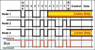
If two or more nodes start transmitting messages at the same time, the arbitration mechanism is applied to guarantee that one of these messages can be sent successfully according to the priority.
Priorities
The CAN IDENTIFIER defines a static message priority during bus access.
CAN Bus Wire Solution
| Bus length [m] | Bus cable | Termination resistance [Ω] | Baudrate | |
|---|---|---|---|---|
| Length-related resistance [mΩ/m] | Wire cross-section [mm2] | |||
| 0 ~ 40 | 70 | 0.25 ~ 0.34 | 124 | 1000 at 40 m |
| 40 ~ 300 | <60 | 0.34 ~ 0.6 | 150 ~ 300 | >500 at 100 m |
| 300 ~ 600 | <40 | 0.5 ~ 0.6 | 150 ~ 300 | >100 at 500 m |
| 600 ~ 1000 | <26 | 0.75 ~ 0.8 | 150 ~ 300 | >50 at 1 km |
| Wire cross-section[mm2] | Maximum length [m] | ||
|---|---|---|---|
| Node = 32 | Node = 64 | Node = 100 | |
| 0.25 | 200 | 170 | 150 |
| 0.5 | 360 | 310 | 270 |
| 0.75 | 550 | 470 | 410 |
Example:
If user use Baudrate 100 kbit/s and wire cross-section 0.5 mm2, the maximum length can arrive to 500 m. But the maximum length is in inverse proportion to the node number. When the node number is up to 32, the maximum length will down to 360 m.
Fiber Converter
ICP DAS CAN converters are used to establish a physical coupling of two or more communication interface, and are infrastructure components with which complex network structures can be implemented. They can be used to implement the data conversion between CAN and COM, USB or Ethernet interface. By selecting the necessary CAN converters, users can control and integrate the data exchange and transmission between multi-interfaces easily.

| Model | Fiber Converter | |||||||
|---|---|---|---|---|---|---|---|---|
| Module Name | I-2533CS-FD | I-2533T-FD | I-2533CS | I-2533CS-60 | I-2533CS-A *note1 |
I-2533
|
I-2532
|
|
| I-2533CS-B *note1 |
||||||||
| CAN Interface | ||||||||
| Module Type |  |
 |
 |
 |
 |
 |
 |
|
| Baud Rate (bps) | CAN bit rates: 10 ~ 1000 kbps, CAN FD bit rates for data field: 100 ~ 10000 kbps | 10 k ~ 1 M and user-defined | 10 k ~ 1 M and user-defined | 10 k ~ 1 M and user-defined | 10 k ~ 1 M and user-defined | 10 k ~ 500 k | ||
| CAN Filter | Yes | Yes | Yes | Yes | Yes | No | ||
| 120Ω Terminal Resistor | Built-in | Built-in | Built-in | Built-in | Built-in | Built-in | ||
| Isolation | 3000 VDC for DC-to-DC, 2500 Vrms for photo-couple | |||||||
| Specification | ISO 11898-2, CAN 2.0A/B and FD | ISO 11898-2, CAN 2.0A and CAN 2.0B | ||||||
| Propagation Delay | 190μs *note2 | 190μs *note2 | 190μs *note2 | 190μs *note2 | 250μs *note2 | < 120 ns | ||
| Fiber Interface | ||||||||
| Type | SC Duplex type ; Single mode ; 100Base-FX; | ST Duplex type ; Multi-mode ; 100Base-FX; | SC Duplex type ; Single mode ; 100Base-FX; | SC type ; Single mode ; 100Base-FX; | ST (Multi-mode) | ST (Multi-mode) | ||
| Wave Length (nm) | 1310 | TX: 1310, RX: 1550 for I-2533CS-A TX: 1550, RX: 1310 for I-2533CS-B | 850 | 850 | ||||
| Fiber Cable (μm) | 8.3/125, 8.7/125, 9/125 or 10/125 | 50 / 125, 62.5 / 125 or 100 / 140 | 8.3/125, 8.7/125, 9/125 or 10/125 | 50 / 125, 62.5 / 125, 100 / 140 | 50 / 125, 62.5 / 125, 100 / 140 | |||
| Max. Fiber Distance (km) | 30 km | 2 km | 30 km | 60 km | 15 km | 2 km | 1.4 km | |
| Misc. | ||||||||
| Topology | One-to-One One-to-Many | One-to-One | One-to-One | |||||
| Work with Fiber Switch | Yes | Yes | Yes | No | No | |||
| Extend CAN bus Distance | Yes | Yes | Yes | Yes | No | |||
| Repeat CAN bus signal | Yes | Yes | Yes | Yes | No | |||
| Integrate two different networks | Yes | Yes | Yes | Yes | No | |||
| *note1: The I-2533CS-A and I-2533CS-B are a couple and must be used in pairs in CAN Bus applications.
|
||||||||
Repeater
| Model | CAN Bus Repeater | ||||||
|---|---|---|---|---|---|---|---|
| Module Name | I-7531-FD-G | I-7531-G | I-7532-G
|
I-7532M-FD
|
I-2534
|
I-5534-M
|
|
| I-7531-FD-UTA-G | I-7531-UT-G | ||||||
| CAN Interface | |||||||
| Module Type |  |
 |
 |
 |
 |
 |
|
| Connector | Screwed terminal block | Screwed terminal block | Screwed terminal block | Screwed terminal block | Screwed terminal block | 9-pin male D-Sub | |
| Channel number | 2 | 2 | 2 | 2 | 4 | 4 | |
| Baud Rate (bps) | CAN bus: 5 k ~ 800 k CAN FD: Arbitration rate up to 1000 k, data rate up to 8000 k |
5 k ~ 800 k | 5k ~ 1M bps and user-defined | CAN bit rates: 10 ~ 1000 kbps, CAN FD bit rates for data field: 100 ~ 10000 kbps |
5k ~ 1M bps and user-defined | 5k ~ 1M bps and user-defined | |
| CAN Filter | No | No | Yes | Yes | Yes | Yes | |
| Isolation | 3000 VDC for DC-to-DC, 2500 Vrms for digital isolation | 3000 VDC for DC-to-DC, 2500 Vrms for photo-couple | |||||
| 120Ω Terminal Resistor | Built-in | Built-in | Built-in | Built-in | Built-in | Built-in | |
| Propagation Delay | 175ns | 200 ns | 134 us ~ 30 ms *note1 | 142 μs ~ 13.8 ms *note2 | 240 us ~ 1360 us *note1 | 240 us ~ 1360 us *note1 | |
| Misc. | |||||||
| Extend CAN bus Distance | No | No | Yes | Yes | Yes | Yes | |
| Repeat CAN bus signal | Yes | Yes | Yes | Yes | Yes | Yes | |
| Integrate two CAN networks at different baud rate |
No | No | Yes | Yes | Yes | Yes | |
| *note1: The propagation delay depends on the CAN Bus baud rate and the CAN message format. The minimum delay is [ 11-bit ID and 8-byte data @ 1M bps ] The maximum delay is [ 29-bit ID and 8-byte data @ 5k bps ] *note2: The propagation delay depends on the CAN Bus baud rate and the CAN message format. The minimum delay is [ 11-bit ID and 8-byte data @ 1M bps ] The maximum delay is [ 29-bit ID and 8-byte data @ 10k bps ] |
|||||||
Converter
| Model | CAN to COM Converter series products | |||||||
|---|---|---|---|---|---|---|---|---|
| Module Name | I-7530-G | I-7530T-G | tM-7530 | tM-7530A | I-7530A-G | I-7530A-MR-G | I-7530-FT-G | |
| CAN Interface | ||||||||
| CAN Specification | ISO-11898-2 | ISO-11898-2 | ISO-11898-2 | ISO-11898-2 | ISO-11898-2 | ISO-11898-3 | ||
| Baud Rate (bps) | 10k ~ 1M bps | 10k ~ 1M bps | 10k ~ 1M bps and user-defined | 10k ~ 1M bps | 10k ~ 1M bps and user-defined |
10 k ~ 125 k | ||
| CAN Filter | Yes | Yes | Yes | Yes | Yes | Yes | ||
| CAN Isolation | 3000 VDC for DC-to-DC, 2500Vrms ~ 3750Vrms for photo-couple | None | ||||||
| Terminal Resistor | Built-in 120Ω | Built-in 120Ω | None | Yes | Built-in 120Ω | Built-in 120Ω | Built-in 1kΩ | |
| Max FPS (@1M bps) | 279 ~ 360 | 279 ~ 360 | 423~519 | 279 ~ 360 | 370 ~ 1250 | 279 ~ 360 | ||
| CAN FIFO | 1000 frames | 1000 frames | 256 frames | 1000 frames | 128 frames | 1000 frames | ||
| UART Interface | ||||||||
| UART | RS-232 | RS-232 | RS-232 | RS-232 / RS-485 / RS-422 (can't be used simultaneously) |
RS-232 | |||
| Baud Rate (bps) | 110 ~ 115200 | 110 ~ 115200 | 110 ~ 230400 | 110 ~ 115200 | 110 ~ 230400 | 110 ~ 115200 | ||
| Connector | 9-pin female D-Sub | 9-pin female D-Sub | 9-pin female D-Sub | Screwed terminal block | Screwed terminal block | 9-pin female D-Sub | ||
| UART FIFO | 900 frames | 900 frames | 256 bytes | 900 frames | 256 bytes | 900 frames | ||
| Misc. | ||||||||
| UART / CAN Conversion | Half-Duplex | Half-Duplex | Full-Duplex | Half-Duplex | Full-Duplex | Half-Duplex | ||
| Propagation Delay | < 3.5 ms | < 3.5 ms | < 3.5 ms | < 3.5 ms | -- | < 3.5 ms | ||
| UART Transparent Communication | One-to-One One-to-Many |
One-to-One One-to-Many |
One-to-One One-to-Many |
One-to-One One-to-Many |
One-to-One One-to-Many |
One-to-One One-to-Many |
||
| Modbus RTU Slave | No | No | No | No | Modbus RTU Slave | No | ||
| Model | CAN FD to COM Converter series products |
|---|---|
| Module Name | I-7530A-MR-FD |
| CAN Interface | |
| CAN Specification | ISO-11898-2 |
| Baud Rate (bps) | CAN bit rates: 10 ~ 1000 kbps,CAN FD bit rates for data field: 100 ~ 10000 kbps |
| CAN Filter | Yes |
| CAN Isolation | 3000 VDC for DC-to-DC, 2500Vrms ~ 3750Vrms for photo-couple |
| Terminal Resistor | Built-in 120Ω |
| Max FPS (@1M bps) | 370 ~ 1250 |
| CAN FIFO | 64 frames |
| UART Interface | |
| UART | RS-232 / RS-485 / RS-422 (can't be used simultaneously) |
| Baud Rate (bps) | 110 ~ 230400 |
| Connector | Screwed terminal block |
| UART FIFO | 256 bytes |
| Misc. | |
| UART / CAN Conversion | Full-Duplex |
| Propagation Delay | -- |
| UART Transparent Communication | One-to-One One-to-Many |
| Modbus RTU Slave | Modbus RTU Slave |
| Model | CAN to Ethernet Converter series products | ||
|---|---|---|---|
| Module Name | I-7540D-G | I-7540D-MTCP-G | I-7540D-WF
|
| I-7540D-UTA-G | I-7540DM-MTCP
|
||
| I-7540DM-UTA | |||
| CAN Interface | |||
| CAN Connector | Screwed terminal block | Screwed terminal block | Screwed terminal block |
| Channel number | 1 | 1 | 1 |
| Baud Rate (bps) | 10k ~ 1M bps and user-defined |
10k ~ 1M bps and user-defined |
5k ~ 1M bps |
| CAN Filter | Yes | Yes | Yes |
| CAN Isolation | 1000 VDC for DC-to-DC 2500 Vrms for photo-couple |
1000 VDC for DC-to-DC 2500 Vrms for photo-couple |
3000 VDC for DC-to-DC 2500 Vrms for photo-couple |
| Terminal Resistor | Built-in 120Ω | Built-in 120Ω | Built-in 120Ω |
| Max FPS (@1Mbps) | 1852 ~ 2244 | 2118 ~ 2241 | 700 |
| CAN FIFO | 1000 frames | 200 frames | 256 frames |
| Ethernet Interface | |||
| Controller | 10/100Base-TX Ethernet Controller (Auto-negotiating, Auto_MDIX) | Wi-Fi (IEEE 802.11b/g) | |
| Protocol | TCP / UDP Socket | Modbus TCP Server | TCP Socket (Client / Server) |
| Socket clients | 25 | 24 | 3 |
| others | Support Virtual COM | Acts as Modbus RTU slave | Infrastructure & Ad-hoc mode |
| Misc. | |||
| CAN Transparent Communication | One-to-One One-to-Many |
One-to-One One-to-Many |
One-to-One One-to-Many |
| Model | CAN FD to Ethernet Converter series products |
|---|---|
| Module Name | ECAN-200-FD |
| CAN Interface | |
| CAN Connector | 9-pin D-sub male |
| Channel number | 2 |
| Baud Rate (bps) | CAN bit rates: 10 ~ 1000 kbps, CAN FD bit rates for data field: 100 ~ 10000 kbps |
| CAN Filter | Yes |
| CAN Isolation | 3000 VDC for DC-to-DC, 2500 Vrms for photo-couple |
| Terminal Resistor | Built-in 120Ω (Dip-Switch) |
| Max FPS | 3000 |
| CAN FIFO | 128 frame |
| Ethernet Interface | |
| Controller | 10/100Base-TX Ethernet Controller (Auto-negotiating, Auto_MDIX) |
| Protocol | TCP Server / UDP Socket |
| Socket clients | 2 (For each port) |
| Misc. | |
| CAN Pair Connection | Yes |
| CAN Transparent Communication | One-to-One One-to-Many |
| Model | USB to CAN Converter series products | |||||
|---|---|---|---|---|---|---|
| Module Name | I-7565M-HS | I-7565-H1-G | I-7565-H2-G | I-7565-G | tM-7565 | |
| CAN Interface | ||||||
| CAN Connector | 8-pin terminal-block | 9-pin male D-Sub | Screwed terminal block | 9-pin male D-Sub | Screwed terminal block | |
| Channel number | 2 | 1 | 2 | 1 | 1 | |
| Baud Rate (bps) | 10k ~ 1M bps and user-defined |
5k ~ 1M bps and user-defined |
5k ~ 1M bps and user-defined |
10k ~ 1M bps and user-defined |
10k ~ 1M bps and user-defined |
|
| CAN Filter | Yes | Yes | Yes | Yes | Yes | |
| CAN Isolation | 3000 VDC for DC-to-DC, 2500 Vrms for photo-couple | |||||
| Terminal Resistor | Built-in 120Ω | |||||
| Max FPS (@1Mbps) | 15000 fps for Tx/Rx | 3000 | 3000 (Total CAN ports) |
279 ~ 360 | 423~519 | |
| CAN FIFO | 512 data frames | 256 frames | 128 frames (for each CAN port) | 1000 frames | 256 frames | |
| USB Interface | ||||||
| USB Type | USB Type B | |||||
| USB Speed | 480Mbps | 12Mbps | 12Mbps | 110 ~ 921600 bps | 110 ~ 230400 bps | |
| Specification | USB 2.0 High Speed | USB 1.1 and USB 2.0 | ||||
| USB FIFO | - | 100 frames | 100 frames | 900 frames | 256 bytes | |
| Power supply | USB | |||||
| Misc. | ||||||
| Send CAN with hardware timer | Yes | Yes | Yes | No | No | |
| Show Error Frame | Yes | Yes | Yes | No | No | |
| Adjustable Bit-Timing | No | Yes | Yes | No | No | |
| Supported OS | Windows 2K/XP/7/8/10 | Windows 2K/XP/Vista/7 (32 & 64 bit)/8.x, and Linux) | Windows 2K/XP/7/8/10 | |||
| Supported LabVIEW | No | Yes | Yes | LabVIEW UART driver | No | |
| Supported InduSoft | No | Yes | Yes | Yes | No | |
| Model | USB to CAN FD Converter series products |
|---|---|
| Module Name | I-7565M-FD |
| CAN Interface | |
| CAN Connector | 8-pin terminal-block |
| Channel number | 2 |
| Baud Rate (bps) | CAN bit rates: 10 ~ 1000 kbps, CAN FD bit rates for data field: 100 ~ 10000 kbps |
| CAN Filter | Yes |
| CAN Isolation | 3000 VDC for DC-to-DC 2500 Vrms for photo-couple |
| Terminator Resistor | Built-in 120Ω |
| Max FPS (@1Mbps) | 3000 fps for Tx/Rx (Total CAN ports) |
| CAN FIFO | 128 frames |
| USB Interface | |
| USB Type | USB Type B |
| USB Speed | 480Mbps |
| Specification | USB 2.0 High Speed |
| USB FIFO | - |
| Power supply | USB |
| Misc. | |
| Send CAN with hardware timer | Yes |
| Show Error Frame | Yes |
| Adjustable Bit-Timing | No |
| Supported OS | Windows 7/8.1/10 |
| Supported LabVIEW | No |
| Supported InduSoft | No |
Gateway
| Model | Gateway | ||
|---|---|---|---|
| Module Name | ECAN-240 | ECAN-240-FD | |
| CAN Interface | |||
| CAN Connector | 9-pin D-sub male | ||
| Channel number | 2 | ||
| Baud Rate (bps) | 10k ~ 1M bps and user-defined | CAN bit rates: 10 ~ 1000 kbps, CAN FD bit rates for data field: 100 ~ 10000 kbps |
|
| CAN Filter | Yes | ||
| CAN Isolation | 3000 VDC for DC-to-DC, 2500 Vrms for photo-couple | ||
| Terminal Resistor | Built-in 120Ω (Dip-Switch) | ||
| CAN FIFO | 256 frame | 128 frame | |
| Ethernet Interface | |||
| Controller | 10/100Base-TX Ethernet Controller (Auto-negotiating, Auto_MDIX) | ||
| Socket clients | 8 | 4 | |
| Misc. | |||
| Web configuration | Yes | Yes | |
| Modbus TCP Server | Yes | Yes | |
| Modbus TCP Client | Yes | No | |
| CAN pair connection | Yes | NO | |
| TCP/UDP to CAN transparent | Yes | NO | |
uPACs
The palm size PACs (Programmable Automation Controller) includes I-7188XBD-CAN, uPAC-7186EXD-CAN and uPAC-5001D-CAN2. With abundant and various peripherals and communication ports, the PAC can integrate different communication interface, like CAN bus, RS-232, RS-485, Ethernet and so on. In order to increase the modules openness and applications fl exibility, the PAC provides MiniOS7, a DOS-like real-time single-task operation system for adapting to all kinds of needs. Users can develop application programs via C/C++ compiler.
 |
 |
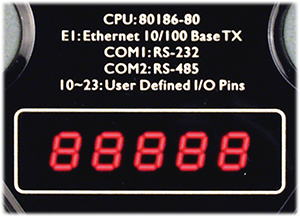 |
|
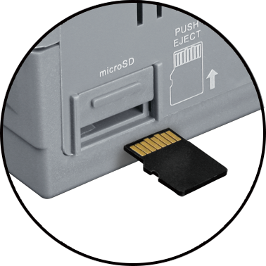
Unique 64-bit Hardware microSD |
Built-in RTC - Real Time Clock |
5-Digit 7-Segment LED Display |
microSD expansion |
| Model | CAN Bus uPAC | ||
|---|---|---|---|
| Module Name | I-7188XBD-CAN-G | uPAC-7186EXD-CAN-G | uPAC-5001D-CAN2 |
| CPU Module | |||
| CPU | 80188, 40 MHz or compatible | 80186, 80 MHz or compatible | 80186 or compatible (16-bit and 80 MHz) |
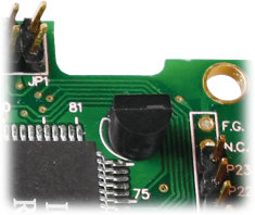
| 64-bit Hardware Serial Number | Yes | Yes | Yes |
| EEPROM | 2 KB (8 blocks) | 16 KB (64 blocks) | 16 KB (64 blocks) |
| Flash | 512 KB | 512 KB | 512 KB |
| NVRAM | 31 bytes | 31 bytes | 31 bytes |
| SRAM | 512 KB | 512 KB | 512 KB |
| Real Time Clock | Yes | Yes | Yes |
| Watchdog Timer | Yes( 0.8 second) | Yes( 0.8 second) | Yes( 0.8 second) |
| Storage Expansion | -- | -- | Yes, support up 32 GB microSD card |
| COM Ports | |||
| Ports | 1 x RS-485, 1 x RS-232/RS-485 | 1 x RS-232, 1 x RS-485 | 1 x RS-232, 1 x RS-485 |
| Baud Rate | 115200 bps Max. | 115200 bps Max. | 115200 bps Max. |
| Ethernet | |||
| Ports | -- | 1 x RJ-45, 10/100 Base-TX | 1 x RJ-45, 10/100 Base-TX |
| CAN | |||
| Controller | NXP SJA1000T | NXP SJA1000T | NXP SJA1000T |
| Ports | 1 | 1 | 2 |
| Baud Rate | 5 k ~ 1 M bps | 5 k ~ 1 M bps | 5 k ~ 1 M bps |
| Isolation | 1000 VDC for DC-to-DC, 2500 Vrms for photo-couple | 1000 VDC for DC-to-DC, 2500 Vrms for photo-couple | 1000 VDC for DC-to-DC, 2500 Vrms for photo-couple |
| Terminal Resistor | Jumper for 120 Ω terminal resistor | Jumper for 120 Ω terminal resistor | Jumper for 120 Ω terminal resistor |
| Specification | ISO-11898-2, CAN 2.0B | ISO-11898-2, CAN 2.0B | ISO-11898-2, CAN 2.0B |
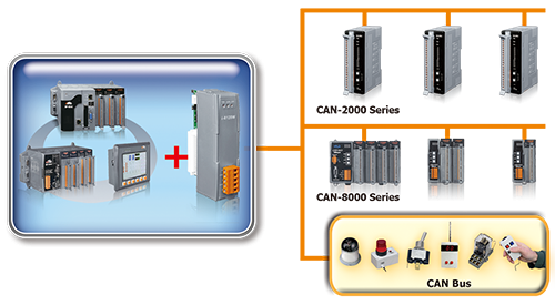
These CAN bus communication modules are the solutions to the various CAN application requirements in PAC family with rich CAN bus protocols. For the especial CAN bus applications, the I-8120Wand I-87120 are designed for users to apply in PAC series. The default firmware of I-8120W and I-87120 provides the transmission and reception of CAN bus messages in PAC. In addition, users can design the specific firmware in these modules to reduce the loading of the PAC in C language.
| Model | PAC CAN slot modules | |
|---|---|---|
| Module Name | I-8120W-G | I-87120-G |
| CAN Interface | ||
| Module Communication | Parallel Bus | Serial Bus |
| CAN Connector | Screwed terminal block | Screwed terminal block |
| Channel number | 1 | 1 |
| Baud Rate (bps) | 10k ~ 1M bps and user-defined |
10k ~ 1M bps and user-defined |
| CAN Filter | Yes | Yes |
| CAN Isolation | 1000 VDC for DC-to-DC 2500 Vrms for photo-couple |
1000 VDC for DC-to-DC 2500 Vrms for photo-couple |
| Terminal Resistor | Built-in 120Ω | Built-in 120Ω |
Communication Board
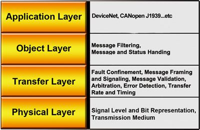
Hardware Architecture

Software Architecture

| Model | High performance CAN card | ||||
|---|---|---|---|---|---|
| Module Name | PEX-CAN200i-D | PISO-CAN100U-D | PISO-CAN200U-D | PISO-CAN400U-D | PISO-CAN800U-D
|
| PEX-CAN200i-T | PISO-CAN100U-T | PISO-CAN200U-T | PISO-CAN400U-T | ||
| Hardware | |||||
| PC Bus Interface | X1 PCI Express | Universal PCI | Universal PCI | Universal PCI | Universal PCI |
| On-board CPU | None | None | None | None | None |
| CAN Interface | |||||
| Channel number | 2 | 1 | 2 | 4 | 8 |
| Baud Rate (bps) | 10k ~ 1M bps and user-defined | ||||
| CAN Filter | Yes | Yes | Yes | Yes | Yes |
| CAN Isolation | 1000 VDC for DC-to-DC; 2500 Vrms for photo-couple | ||||
| Terminal Resistor | Built-in 120Ω | Built-in 120Ω | Built-in 120Ω | Built-in 120Ω | Built-in 120Ω |
| Driver | |||||
| DLL Library | VB 6.0, VC++ 6.0, BCB 6.0, Delphi 4.0, C#.Net, VB.Net | ||||
| Windows Driver | Windows XP/7/8/10 (32-bit/64-bit OS) | ||||
| Linux Driver | Linux 2.6.x ~ 3.2.20 | ||||
| SocketCAN Driver | Yes | Yes | Yes | Yes | None |
| RTX Driver | Yes | Yes | Yes | Yes | None |
| ActiveX Driver | Yes | Yes | Yes | Yes | Yes |
| InduSoft Driver | Yes | Yes | Yes | Yes | Yes |
| LabVIEW Driver | Yes | Yes | Yes | Yes | Yes |
| OPC Server | Yes | Yes | Yes | Yes | Yes |
| VxCAN Driver | Yes | Yes | Yes | Yes | Yes |
| Software & Toolkit | |||||
| Software & Toolkit | Yes | Yes | Yes | Yes | Yes |
| Yes | Yes | Yes | Yes | Yes | |
| Model | High performance CAN FD card | |
|---|---|---|
| Module Name | PISO-CAN200U-FD-D | PISO-CAN400U-FD-D |
| PISO-CAN200U-FD-T | PISO-CAN400U-FD-T | |
| Hardware | ||
| PC Bus Interface | Universal PCI | Universal PCI |
| On-board CPU | None | None |
| CAN Interface | ||
| Channel number | 2 | 4 |
| Baud Rate (bps) | CAN bit rates: 10 ~ 1000 kbps, CAN FD bit rates for data field: 100 ~ 10000 kbps |
|
| CAN Filter | Yes | |
| CAN Isolation | 3000 VDC for DC-to-DC, 2500 Vrms for photo-couple | |
| Terminal Resistor | Built-in 120Ω | |
| Driver | ||
| DLL Library | C#.Net, VB.Net, VC++.Net | |
| Windows Driver | Windows 7/8/10 (32-bit/64-bit OS) | |
| Linux Driver | No | No |
| InduSoft Driver | No | No |
| LabVIEW Driver | No | No |
| Software & Toolkit | ||
| PISO-CANFD Utility | Yes | Yes |
| Model | High performance PCI-104/PC-104+ CAN Card | ||
|---|---|---|---|
| Module Name | PCM-CAN100 | PCM-CAN200 | PCM-CAN200P |
| Hardware | |||
| PC Bus Interface | PCI-104 | PCI-104 | PC-104+ |
| On-board CPU | None | None | None |
| CAN Interface | |||
| Channel number | 1, and the other for bypass | 2 | 2 |
| Baud Rate (bps) | 10k ~ 1M bps and user-defined | ||
| CAN Filter | Yes | Yes | Yes |
| CAN Isolation | 1000 VDC for DC-to-DC; 2500 Vrms for photo-couple | ||
| Terminal Resistor | Built-in 120Ω | Built-in 120Ω | Built-in 120Ω |
| Driver | |||
| DLL Library | VB 6.0, VC++ 6.0, BCB 6.0, Delphi 4.0, C#.Net, VB.Net | ||
| Windows Driver | Windows XP/7/8/10 (32-bit/64-bit OS) | ||
| Linux Driver | Linux 2.6.x ~ 3.2.20 | ||
| SocketCAN Driver | Yes | Yes | Yes |
| RTX Driver | Yes | Yes | Yes |
| ActiveX Driver | Yes | Yes | Yes |
| InduSoft Driver | Yes | Yes | Yes |
| LabVIEW Driver | Yes | Yes | Yes |
| OPC Server | Yes | Yes | Yes |
| VxCAN Driver | Yes | Yes | Yes |
| Software & Toolkit | |||
| VxCAN Utility | Yes | Yes | Yes |
| CANcheck | Yes | Yes | Yes |
| Model | Intelligent PCI/PCI-104 CAN Card | ||
|---|---|---|---|
| Module Name | PISO-CM100U-D | PCM-CM100-D | PISO-CM200U-D |
| PISO-CM100U-T | PISO-CM200U-T | ||
| Hardware | |||
| PC Bus Interface | Universal PCI | PCI-104 | Universal PCI |
| On-board CPU | 80186, 80 MHz | 80186, 80 MHz | 32-bit MCU |
| On-board OS | MiniOS7 | MiniOS7 | -- |
| On-board Firmware | Programable | Programable | -- |
| Firmware SDK | Turbo C 2.01 , TurboC++ 1.01 , Borland C++ 3.01 | -- | |
| CAN Interface | |||
| Channel number | 1 | 1 | 2 |
| Baud Rate (bps) | 10k ~ 1M bps and user-defined | ||
| CAN Filter | Yes | Yes | Yes |
| CAN Isolation | 1000 VDC for DC-to-DC; 2500 Vrms for photo-couple | 3000 VDC for DC-to-DC; 3000 Vrms for photo-couple |
|
| Terminal Resistor | Built-in 120Ω | Built-in 120Ω | Built-in 120Ω |
| Driver | |||
| DLL Library | VB 6.0, VC++ 6.0, BCB 6.0, Delphi 4.0, C#.Net, VB.Net | C#.Net,VB.Net, VC++.Net | |
| Windows Driver | Windows XP/7/8/10 (32-bit/64-bit OS) | Windoes XP, Win7/8.1/10 (32-bit/64-bit OS) |
|
| InduSoft Driver | Yes | Yes | -- |
| LabVIEW Driver | Yes | Yes | -- |
Data Logger
The CAN-Logger series devices (CAN-Logger100/CAN-Logger200) are high-performance intelligent CAN bus data logger device with one/two CAN port that can help to make data collection and to process on a CAN bus network easier and quicker. The powerful CPU of the CAN-Logger devices provide the accurately time-stamp for each CAN message and supports storage media like SD or SDHC type flash for saving these CAN messages that is useful to analysis and diagnostic the CAN Bus network. In order to enhance the portability of the CAN-Logger200, this module is powered by the USB interface or M12 connectors of CAN bus interface. The CAN-Logger devices use the standard USB HID driver of the Windows system.

Feature:
- Compatible with CAN specification 2.0 parts A and B
- 2500 Vrms photocoupler isolation on the CAN side
- Full compatible with the ISO 11898-2 standard
- Supports CAN bus acceptance filter configuration
- Max. CAN data flow for a single channel is 15000 fps
- Programmable CAN bus baud rate from 10 kbps ~ 1Mbps
- USB 2.0 High Speed Compatibility
- Supports 4 to 32 GB SDHC type flash for saving CAN messages
- Built-in jumper for the 120 Ω terminal resistor of the CAN side
- Power by the USB port or CAN port
- 3 kV galvanic isolation for the CAN port
- Provides a configuration utility that can be used to transmit/receive CAN messages
|
CAN Bus Data Logger |
|
| Model | Description |
|---|---|
| CAN-Logger100 | 1-port CAN Bus Data Logger Device |
| CAN-Logger200 | 2-port CAN Bus Data Logger Device |
Software
| Item | Description |
|---|---|
| CAN OPC Server | This is the OPC server for all the SCADA like LabVIEW, iFix, DASYLab and etc. By using the OPC server, the users be able to control any CAN devices via the famous SCADA. [more...] |
| VxCAN Driver | The VxCAN driver is the virtual CAN driver for all CAN converters and CAN master products. Even using different products, the users could use the same APIs to develop any CAN applications. [more...] |
| VxCAN Utility | The VxCAN Utility, a diagnostic and test software tool, is designed to unleash the power of all CAN products of ICP DAS. It is based on the Virtual CAN technique which creates the virtual CAN ports to match the physical CAN interfaces of the installed products. [more...] |
| InduSoft Driver |
The IndoSoft is one of the famous and high performance SCADA. Nowaday, it supports the CAN, CANopen and DeviceNet driver for all the coresponding converter or master series products. [more...] |
| CANcheck | This is the software for diagnosing and testing the user's CAN devices. The graphical interface is ready-made and easy to operate. [more...] |
| CAN Test Tool | The CAN test tool can help users to test the CAN communication of CAN series of ICP DAS by the simple steps. This tool is based on VxCAN driver and supports most of all CAN products of ICP DAS [more...] |
RTX Driver |
In order to satisfy the users to apply the RTX system, ICPDAS provides the RTX driver for PISO-CAN series CAN card. If users want to combine the CAN communication interface in their time-critical system, the RTX driver of the PISO-CAN series CAN cards can help them to do this easily and quickly. Furthermore, the name and parameters of the APIs in the RTX driver are the same as in the Windows driver. Users don’t need to pay more efforts to study how to use the APIs of the RTX driver if they have used the Windows driver before. The RTX driver increases the additional worth of the PISO-CAN series CAN cards, and satisfies the users to get the highly real-time system. By owing to the feature of high price performance and highly real-time, PISO-CAN series CAN cards will be applied in more wide and more variant CAN applications. |
SocketCAN Driver |
The SocketCAN is based on the Linux operating system, and it contains the implementation interface of the network stack and the hardware driver. The hardware manufacturers program the hardware driver for the SocketCAN, and the network stack provides the standard BSD Socket APIs for users. Therefore, from the users’ point of view, they can easily and quickly program their applications without being familiar with the various APIs of the different hardware interface through the SocketCAN network stack. |
ActiveX Tool |
In order to use PISO-CAN200/400 easier, we provide a PISOCANX ActiveX component (OCX). It is a useful element to develop the PISO-CAN200/400 application on different program development platform, and it also help users to reduce their development period. Specially, users can use this in their SCADA softwares which support ActiveX technology. It would be possible to use SCADA software to control or monitor CAN devices. If users want to get PISOCANX, it will be found after installing the PISO-CAN200/400 driver with 1.16 version or later. |
LabVIEW Tool |
In order to apply the PISO-CAN200/400 to CAN network with NI LabVIEW, we provides a LabVIEW 7/7.1 toolkit for the purpose. It is a useful tool to develop the CAN-relative application in NI LabVIEW environment by using PISO-CAN200/400. It is easy to use and can help user to rapidly reduce their program development cycle. If users want to develop a LabVIEW industrial application with CAN network, the LabVIEW CAN driver is very helpful. |
DASYLab Tool |
In order to easy to use the PISO-CAN200/400 to CAN network for user. We provides a DASYLab version 8.0 toolkit for the purpose. It is a useful tool to develop the CAN-relative application in DASYLab environment by using PISO-CAN200/400. It can help user to rapidly reduce their program development cycle. If users want to develop a DASYLab industrial application with CAN network, the DASYLab CAN driver is very helpful. |
